Discover the Quick Mask Mode
July 4, 2009 at 12:37 pm | Posted in GrApHiX, PhOtOsHoP | Leave a commentTags: Discover the Quick Mask Mode
This is an important tutorial because it is introducing you to the quick mask. The quick mask is a powerful way to get great selections accurately and it’s very flexible. First start off with the lasso tool

and make a very loose selection around an object

Now that you have made a selection, you can view it at any time (and do further editing) in the quick mask mode. To enter the quick mask mode press the icon as shown right here (you can also toggle between regular and quick mask modes with the ‘Q’ keyboard shortcut).

When you enter the quick mask mode you get a rubylith. This shows that areas that are de-selected in Red and the areas that are selected as untouched or clear.

You can further edit your selection in process (the quick mask becomes a temporary channel in the Channels palette and is gone when you exit the mode) by a number of ways including selection and filling (combined), gradient and using the brush tool (most common). Select the brush tool while you are in quick mask mode.

You can change the size of your brush in the brush dialog box in the options bar. Basically what you’re going to do is ‘paint in’ the areas that you want to deselect.

In order to do this you also have to understand that black must be the foreground color in order to paint in red (don’t let this confuse you…if the rubylith was black you wouldn’t see anything) to deselect. To RESELECT you use white as your foreground color with the paintbrush. This is a very important concept I refer to often:
Black hides pixels. White buys them back. It could take you a long time to get comfortable with this in an operational proficiency. I cover dozens of tutorials on quick masking and getting great selections in my Basic Photoshop DVD Training; this will help you fully grasp and know how to use all of these tools like a pro.
Also, when you choose any shade between white and black you will get different levels of opacity in the resulting selection. The closer to black you are the more invisible the pixels and the closer to white the shade of grey, the more visible the pixels will be.  White is pure original pixels (“buys back” your pixels)

and black is pure hidden (masked) or invisible.

Because the quick mask is essentially a grayscale alpha channel, no other colors are involved, just white to black and shades of grey in between. These are what you will ‘paint’ with in order to select or deselect.
Now just take your brush with black as the foreground color and fill in the rest of the sky carefully.


The rubylith just shows you the actual job that you are doing. Feel free to lower the size of the brush to get into smaller areas (use the bracket keys [ ] to make the brush size larger or smaller).


If you accidentally (or purposefully) spillover and deselect an area with red use the shortcuts of D,X to switch and get white as your new foreground color. With white remember you are buying back pixels, or preserving them in the ultimate selection, so just eraser the red rubylith to where it spills over into your mountain or selection object.

It might take a few minutes depending on the type of selection job and complexity (even for pro’s) but learning this ‘quick mask’ method is really a time saver. Try using the rectangular marquee to get a selection like this (yikes). Remember that you can also combine other selection tools and you can use the gradient tool, making selections in the quick mask mode and then filling with either white or black or your shade of grey. You can also enter the quick mask mode from scratch without first making any selection (not recommended) and then you can use a large brush to just start deselecting areas to close in around your selection with black as your foreground color.
Press the Edit in standard mode button

or Q to exit quick mask, delete the temporary channel (which will return once you enter again) and see the selection job that you have created.
You can always enter quick mask mode again to keep working on or editing your selection. I much prefer the quick mask mode personally than to edit selections by making them into work paths and using pen editing tools. With the brushes it usually gets a great selection every time with nice clean edges.

Here is the view of the quick mask mode in the Channels palette where the temporary channel (alpha) is created. Note that the black area is deselected and the white area is the ‘selected’ portion. The rubylith simply allows you to view your selection job in progress.

Remember that you can also right click in standard mode (with selection tools such as the marquee…) to choose make work path. This is covered in another tutorial and is another (harder) way of editing your selections/paths.

To fully master the quick mask mode and learn how to get pristine selections every time grab a hold of my Basic Photoshop video training. It’s got hundreds of tutorials and many featuring the quick mask and getting selections, including combining different selection tools together.
How to Write Plug-Ins for Adobe After Effects
July 2, 2009 at 2:32 am | Posted in Adobe After Effects, GrApHiX | Leave a commentTags: Creating custom video f/x for Adobe's bestselling video-compositing program is surprisingly easy, How to Write Plug-Ins for Adobe After Effects
Creating custom video f/x for Adobe’s bestselling video-compositing program is surprisingly easy
If you’ve ever marveled at the stunning visuals in those 15-second bumpers for shows on the Discovery Channel, A&E, or MTV, it may surprise you to know that many of them were created on the Mac, using off-the-shelf software – namely, Adobe After Effects.
After Effects is the Swiss Army knife of video post-production, offering a powerful, intuitive, layer-based approach to compositing in which variable-opacity masks and keyframe-based motion control can be used to create stunning video effects.
As with Photoshop (Adobe’s 2D graphics editor), much of the power of After Effects comes from its extensive use of plug-ins – external code resources that augment the functionality of the core program. Plug-ins for After Effects are similar to plug-ins for Photoshop in that most are image filters that batch-process pixels to achieve effects like blurring, sharpening, contrast enhancement, etc. The big difference, of course, is that plug-ins for After Effects operate not only in the image domain but the time domain as well. An After Effects filter may be invoked dozens, hundreds, or even thousands of times, sequentially, as frames of video are processed into final footage. An effect may last a split-second, or several minutes. During that time, individual filter parameters may ramp up or down or undergo any number of changes (or no change at all).
Since After Effects filtering occurs entirely offline, the effect can be as simple – or as computationally intense – as the programmer wants it to be; the calculations don’t have to occur in real time. (This is in contrast to QuickTime-API effects, which are implemented as image decompressors and must occur in real time.) This means an After Effects filter can tackle some fairly lofty tasks, such as:
- Synthesis of complex, animated textures for use as backgrounds. (This is a so-called zero-source type of effect.)
- Traditional single-source image filtering. (Blurring, sharpening, contrast enhancement, gamma adjustment, color-shifting, addition or removal of noise, etc.)
- Dual-source image filtering. (Wipes, fades, dissolves; complex matte effects.)
- Warping, morphing, and distortion-mapping effects.
- 3D effects.
- Particle systems and physics simulations.
- Audio processing. (New in version 4.0.)
As with Photoshop plug-ins, writing plug-ins for After Effects offers a number of advantages for the graphics programmer, including rapid development time, a stable host-program environment, freedom from having to worry about file I/O or format conversions, automatic Undo, automatic data buffering, and good code portability (thanks to a cross-platform API in which device and OS dependencies have been abstracted out). In addition, the After Effects plug-in API lets you build a solid, cross-platform user interface in minimal time, with minimal code. And you don’t have to know a thing about QuickTime. The net result is that you’re free to concentrate on special effects programming instead of worrying about event-loop code, file I/O, and other non-graphics issues.
But beyond all that, writing After Effects plug-ins is just plain fun. Creating Photoshop filters can be a blast, but the first time you see a custom video effect of your own design come alive on the screen, you’ll be transfixed, like a deer in headlights. In fact, you may never look at video the same way again.
The After Effects SDK
To develop plug-ins for After Effects, you’ll need a copy of the After Effects plug-in SDK, which is available from Adobe’s web site (see <http://partners.adobe.com/asn/developer/sdks.html>); or you can get it on CD-ROM by joining the Adobe Solutions Network Developer Program (formerly the Adobe Developers Association). Joining the ASN Developer Program is worth considering, because for $195/yr. you not only get CD-ROM updates for all the current Graphics & Publishing SDKs (i.e., SDKs for Photoshop, Premiere, After Effects, Illustrator, InDesign, etc.), but you also qualify to obtain a full version of any Adobe product for just $99 – including After Effects itself.
If you can’t get the SDK on CD, plan on downloading several megabytes of material from Adobe’s web site. You’ll end up with around four megs of quite useful .pdf documentation, plus an equal amount of C/C++ sample code and headers. Most of what you need to know is covered in the 82-page AE 4.0 SDK Guide, updated in January ’99 to reflect the changes that occurred with After Effects 4.0. Additional docfiles talk about Adobe’s Plug-In Component Architecture (PICA), ‘PiPL’ resources, and sundry other matters.
Compared to the Photoshop plug-in specification (which has become quite complex; see my two-part article in the April and May 1999 issues of MacTech), the After Effects API is lean and mean – a Porsche 911 in a world of London double-decker buses. “But don’t Photoshop and After Effects use the same basic plug-in API?” you may be asking. Actually, the two programs have entirely different plug-in architectures. After Effects does emulate the Photoshop 3.0 plug-in API, but native After Effects plug-ins use a dedicated API which is not recognized by Photoshop. (This shouldn’t come as a surprise, since video effects have a time domain and respond to keyframe and track data – things a Photoshop plug-in wouldn’t know anything about.) Technically, it is possible to make a Photoshop plug-in respond to After Effects keyframes, using a kluge called the ‘ANIM’ resource. The ‘ANIM’ resource spec is described on pages 21-24 of Adobe’s Plug-In Resource Guide (see the SDK), if you’re interested. The advantage of the ‘ANIM’ resource is that if you’ve already written and debugged a Photoshop filter, you can convert it to a video filter by merely crafting a resource rather than writing more code. But in most cases you should write to the After Effects API, which allows access to standard AE user controls and a variety of callbacks that aren’t present in the Photoshop API.
Two Basic Components
There are two basic components to an After Effects plug-in: a ‘PiPL’ resource, and executable code. The ‘PiPL’ (or plug-in property list) resource, as you may recall from my article on Photoshop plug-ins (MacTech, April ’99), is an extensible structure for representing a plug-in’s metadata – information about the plug-in’s version, mode of operation, menu and submenu names, image modes supported (RGB, CMYK, etc.), how the host program should interpret alpha channel data, etc. The detailed specification is given in Adobe’s Plug-In Resource Guide. In addition, the SDK contains Rez scripts and compiled resources for the example projects. Resorcerer recognizes ‘PiPL’ resources and will be a help in editing them. ResEdit is no help at all.
The reason the ‘PiPL’ resource is so important is that this is the first thing the host (After Effects) examines when it scans available plug-ins. It’s how the host locates the plug-in’s entry point and also how it determines whether the file is a legitimate plug-in at all (and if so, which menu it belongs in). Years ago, the plug-in’s filetype was the determining factor in identifying plug-ins, but that’s not how it works any more. For a plug-in to work right, the ‘PiPL’ has to be correct.
After Effects now supports three main plug-in types: Filter, Input/Output, and (with version 4.0) Foreign Project File plug-ins. (The latter was created so that After Effects could import Premiere projects.) The ‘PiPL’ tells After Effects what kind of plug-in it is dealing with, which menu or submenu it should appear in, and what name to give it in the submenu.
In terms of filetypes, a native After Effects plug-in will have a filetype of ‘eFKT’ (and a creator type of ‘FXTC’), but this is merely a convention, not a requirement. In terms of code, an After Effects plug-in is compiled as a Shared Library module on the Mac or a DLL under Windows, with an entry point of main; and as a practical matter all After Effects filters for the Mac are now compiled as PPC-native, since the After Effects SDK no longer supports 68K code (as of version 4.0).
How a Plug-in Works
When After Effects is launched, it looks for plug-ins in all subdirectories of its path, recursively descending up to 10 levels deep. MacOS aliases are resolved and all folders are checked except any with names surrounded in parentheses, such as “(Old Plug-ins)”. Note that no executables are actually loaded at this point; rather, After Effects caches a list of available plug-ins and loads them dynamically as the needarises. Unlike Photoshop, however, After Effects doesn’t unload a plug-in after it is used. That’s because in a piece of video footage, a plug-in might have to be invoked hundreds or even thousands of times, sequentially, and to unload and reload it thousands of times would be inefficient. (Tip: During development, if you need to flush After Effects’ plug-in cache so that you can load a new version of your plug-in at program run time, without having to quit and relaunch After Effects, hold down the Control and Clear keys.)
All After Effects plug-ins have a single entry point, main(), which is called repeatedly with selectors indicating the desired action. The prototype for main() looks like this:
PF_Err main (PF_Cmd  cmd,
		PF_InData  *in_data,
		PF_OutData *out_data,
		PF_ParamList params,
		PF_LayerDef *output,
		void 		 *extra);
The first argument is a selector whose value represents the stage of execution that the plug-in is about to enter.
The second argument to main is a pointer to a large data structure containing host-application state information and hooks to callbacks.
The third parameter is a pointer to a structure that serves as a way for the plug-in to communicate its needs to the host. For example, error messages can be passed back to the host via the return_msg field. (See AE_Effect.h for the complete typedef.)
The params argument is where the plug-in gets access to its user-specified parameter values – for example, the value of sliders or controls in the Effects Control Window (ECW). In other words, all of your user interface info is cached here. We’ll have more to say about this is a minute.
The output parameter points to a PF_LayerDef struct, which contains information about the output image (including a pointer to its data): its dimensions, its rowbytes value, and the extent_hint, which is a Rect giving the bounds of the area that actually needs rendering. (This is often just a subset of the overall image.) Don’t confuse the PF_InData and PF_OutData structs with pointers to pixel data; images are represented by the PF_LayerDef, also sometimes called a PF_World.
Finally, the extra pointer is a special-use parameter that went largely unused prior to After Effects 4.0. It points to different data structures at different times (and garbage, at other times). You’ll only deal with this parameter if you decide to implement custom user interface elements and/or complex custom data types.
The possible selector values for cmd are:
enum {
	PF_Cmd_ABOUT = 0,
	PF_Cmd_GLOBAL_SETUP,
	PF_Cmd_UNUSED_0,
	PF_Cmd_GLOBAL_SETDOWN,
	PF_Cmd_PARAMS_SETUP,
	PF_Cmd_SEQUENCE_SETUP,
	PF_Cmd_SEQUENCE_RESETUP,
	PF_Cmd_SEQUENCE_FLATTEN,
	PF_Cmd_SEQUENCE_SETDOWN,
	PF_Cmd_DO_DIALOG,
	PF_Cmd_FRAME_SETUP,
	PF_Cmd_RENDER,
	PF_Cmd_FRAME_SETDOWN,
	PF_Cmd_PARAMS_UPDATE,
	PF_Cmd_PARAMS_SUPERVISE,
	PF_Cmd_EVENT,
	PF_Cmd_NTRP,
	PF_Cmd_PARAMS_CONVERT,
	PF_Cmd_RESERVED,
	PF_Cmd_NUM_CMDS
};
Of these, most plug-ins will only ever have to respond to PF_Cmd_ABOUT, PF_Cmd_GLOBAL_SETUP, PF_Cmd_PARAMS_SETUP, and PF_Cmd_RENDER. All plug-ins are expected to respond to these four selectors. (The usage of the other selectors is well-documented not only in the SDK docfiles but in the header files as well.) We’ll go over some of these as we step through our code, below.
Code Project: Warbler
Because of the power and sophistication of the API, it’s possible to create a useful After Effects plug-in with less than 400 lines of C code; hence, in this article we’re going to present the entire code for a complete plug-in (also available online at ftp://www.mactech.com). Our sample plug-in, called Warbler, duplicates the function of Adobe’s Displacement Map plug-in, which is not included in the $995 retail distribution suite for After Effects but is included in the $2,195 Production Bundle. Warbler is a displacement-map effect that uses one image layer to distort another layer. The key concept here is that for every pixel of our source image, we check the corresponding pixel of a “map” image, and if the map-image pixel is white, we displace our source-image pixel in one direction, while if the map pixel is black, we displace the source pixel in the opposite direction. (In reality, we don’t push any source pixels around; rather, we index into different parts of the source image – i.e., we displace the offset into our image, rather than the pixel. Also, we don’t rely on black or white pixels in the map image. Instead, we look at the luminance of each pixel, and calculate a displacement value that is proportional to the map pixel’s luminance.) To give a good visual result requires that we resample pixels with subpixel accuracy, which means we need to perform between-pixels interpolation (as discussed in the Photoshop plug-ins article in the May ’99 MacTech). Fortunately, the After Effects API offers a ready-made function that accomplishes this for us.
The effect produced by Warbler is best understood by referring to Figures 1, 2, and 3. Figure 1 shows a test image consisting of a large number of horizontal lines. Figure 2 shows an image of bullseye-style concentric rings which vary sinusoidally in pixel intensity. If we let Figure 2 be our map image (which determines how we “push the pixels around” in Figure 1), the result of applying our Warbler plug-in is the image in Figure 3. Note how the formerly parallel horizontal lines now seem to show concentric waves, like ripples in a pond. This is diplacement mapping.
Bear in mind, of course, that in After Effects, each image is actually a frame in a sequence, which can change over time. By animating the map image, distortions in the source image can be made to animate as well – which means that if you’re clever, you can achieve a variety of interesting visual effects (pond ripples, flag ruffles, puckering, bulging, bending) in the visible layer(s) of a video just by animating an invisible map layer.

Figure 1. Source image.

Figure 2. Map image.

Figure 3. Warbled source image.
Code Walkthrough
Listing 1 gives all the #defines and #includes for our project, along with code for our About handler. By convention, all handler functions are prototyped as
static PF_Err FunctionName (
	PF_InData		 *in_data,
	PF_OutData		 *out_data,
	PF_ParamDef		*params[],
	PF_LayerDef		*output );
even though, in many cases, the passed-in pointers are not used. The return value is always a PF_Err (long) so that user aborts and other error conditions can be passed back, through main(), to the host.
In About(), we make use of the PF_SPRINTF macro (defined in AE_EffectCB.h) to send a DESCRIPTION string back to the host. After Effects responds by putting up a simple modal dialog containing our “about” information. No ‘DITL’ or ‘ALRT’ resources are needed.
Listing 1: About() and #defines
About()
Constants, macros, and includes for our plug-in, plus our About handler.

// INCLUDES
#include "AE_EffectCB.h"
#include "AE_Macros.h"

// DEFINES
#define	NAME	"Warbler"
#define	MAJOR_VERSION		2
#define	MINOR_VERSION		1
#define	BUG_VERSION			0
#define	STAGE_VERSION		PF_Stage_RELEASE
#define	BUILD_VERSION		0

#define LONG2FIX(x) (((long)x)<<16)
#define LUMA(p) \
	(double)(p->red + 2*p->green + p->blue)/(255. * 4.)
#define bias(a,b) \
	PF_POW( (a), PF_LOG(b) / PF_LOG(0.5) )

#define ANGLE_MIN		(-180L << 16)
#define ANGLE_MAX		( 180L << 16)
#define	BIAS_MIN		(655)	// 0.01 Fixed
#define	BIAS_MAX		(1L << 16)
#define	BIAS_BIG_MAX	(10L << 16)
#define	BIAS_DFLT		(6553*5) // about 0.5 Fixed
#define	SHIFT_BLEND_MIN	0L
#define	SHIFT_BLEND_MAX	(1L << 16)
#define	SHIFT_BLEND_DFLT 0L

// PARAMETER DEFINITION CONSTANTS
enum {
	BASE=0,
	DISP_LAYER,
	DISP_ANGLE,
	SHIFT_DISPLACE_AMT,
	SHIFT_GAMMA,
	SHIFT_BLEND,
	SHIFT_NUM_PARAMS
};

#define DESCRIPTION	\
"Displacement mapping based on luminance."

// --------------- About() --------------
static PF_Err About (
	PF_InData		*in_data,
	PF_OutData		*out_data,
	PF_ParamDef		*params[],
	PF_LayerDef		*output )
{

	PF_SPRINTF(out_data->return_msg, "%s,v%d.%d\r%s",
		NAME, MAJOR_VERSION, MINOR_VERSION, DESCRIPTION);

	return PF_Err_NONE;
}
Listing 2 shows the plug-in’s entry point, main(). This routine simply cases out the selector value and dispatches to the appropriate handler function. Warbler responds to just the five selector values shown, ignoring any others that are sent.
Listing 2: main()
main() Dispatch to the appropriate handler and report any errors to the host.
PF_Err main (
	PF_Cmd				cmd,
	PF_InData		*in_data,
	PF_OutData		*out_data,
	PF_ParamDef	*params[],
	PF_LayerDef	*output,
	void					*extra )
{
	PF_Err		err = PF_Err_NONE;

	switch (cmd) {
	case PF_Cmd_ABOUT:
		err = About(in_data,out_data,params,output);
		break;
	case PF_Cmd_GLOBAL_SETUP:
		err = GlobalSetup(in_data,out_data,params,output);
		break;
	case PF_Cmd_PARAMS_SETUP:
		err = ParamsSetup(in_data,out_data,params,output);
		break;
	case PF_Cmd_GLOBAL_SETDOWN:
		err = GlobalSetdown(in_data,out_data,params,output);
		break;
	case PF_Cmd_RENDER:
		err = Render(in_data,out_data,params,output);
		break;
	default:
		break;
	}

	return err;
}
It turns out, our plug-in is comprised of only seven functions altogether: main() itself, the five dispatch functions shown inside main(), and an iteration function called DisplaceImage(), where the real work takes place. We’ve already talked about two of the seven functions. Two more are shown in Listing 3 – namely, GlobalSetup() and GlobalSetdown().
In GlobalSetup(), which gets called when the plug-in is first loaded, we need to do three things: allocate any global data we might need (attaching it to the global_data Handle in the PF_OutData struct), report our version information to the host (via the my_version field of the PF_OutData struct), and set any flags that might be needed to convey our preferences to the host (via out_flags). Warbler doesn’t allocate any memory, so all we do in GlobalSetup() is report the version info and set a flag. It’s necessary to report the version information because After Effects will check this information against the version numbers given in our ‘PiPL’ resource, and if the two don’t match, the plug-in won’t load. (Remember this when debugging!)
The out_flag field of our PF_OutData record can be set to indicate a number of special requests. In our case, we want the image’s output extent, which is the Rect giving the bounds of the portion of the image that’s actually visible. This can save a lot of unnecessary computation when the source image is larger than the active screen area. Other flags can be set to let the host know that (for example) your plug-in wants to receive event messages, generate audio effects, overwrite the input buffer, etc. See the SDK documentation for details.
Listing 3: GlobalSetup() and GlobalSetdown()
GlobalSetup() and GlobalSetdown()
static PF_Err GlobalSetup (
	PF_InData		*in_data,
	PF_OutData		*out_data,
	PF_ParamDef	*params[],
	PF_LayerDef	*output )
{
	PF_Err	err = PF_Err_NONE;

	// We need to let AE know what version we are:

	out_data->my_version =
		PF_VERSION(MAJOR_VERSION,
							MINOR_VERSION,
							BUG_VERSION,
							STAGE_VERSION,
							BUILD_VERSION);

	// We are going to iterate over the output extent,
	// so we need to specify that flag...

	out_data->out_flags |=
		PF_OutFlag_USE_OUTPUT_EXTENT;

	return err;
}

//---------------- GlobalSetdown() ----------------
// This is empty since we haven't allocated any global data.

static PF_Err GlobalSetdown (
	PF_InData		*in_data,
	PF_OutData		*out_data,
	PF_ParamDef	*params[],
	PF_LayerDef	*output )
{
	return PF_Err_NONE;
}
The User Interface
In order to enforce consistent behavior and a consistent appearance among plug-ins, After Effects imposes certain user-interface requirements on filters (which you can certainly circumvent if you want to, although in 99% of cases you’d be foolish to do so). All user interfaces for all effects in a given layer show up in that layer’s Effects Control Window (ECW), which is a kind of master view window in which individual filters appear as vertically stacked panes, with the flow of control going top-to-bottom. (The output of each effect is pipelined to the next effect in the stack – and the Comp Window continuously updates to show the net effect of the stack of filters. No preview pane is necessary inside a filter, because the Comp Window already serves that purpose.) Control elements like checkboxes, sliders, etc. look identical (except for labelling) from one effect to another.
At first blush, all this may sound rather stifling, but in fact there are compensating benefits for the programmer. The main benefit is that you get a user interface virtually for free, because the After Effects plug-in API has provisions for setting up sliders, checkboxes, color pickers, drop-down menus, etc., with very little code. After Effects takes care of all the details of intercepting mouse hits, making sure controls operate correctly, caching all the control settings, linking control settings to keyframes, bounds-checking all parameter values (and presenting validation alerts to the user), and so on. All you have to do is tell After Effects how many of each kind of control you’d like, and in what order they should appear – then at render time, the bounds-checked parameter values are handed to you.
Listing 4 shows how UI controls and their default settings are specified, in the ParamsSetup() function. (This function will be entered whenever a new instance of the plug-in is requested by the user.) The drill here is to declare a PF_ParamDef, zero it out, then start filling in the appropriate fields, starting with the param_type, then call the macro PF_ADD_PARAM(), which tells After Effects to add this parameter to an array of parameters for our plug-in.
The API allows for eleven different types of controls (or parameters), including not only checkboxes and sliders but popup menus, “angle” controls (which give angles in degrees), “point” controls (which give an x, y offset into the image), color pickers, and provisions for custom control types. The one glaring omission in this list is the radio button. (For modal choices, you’re evidently supposed to use a popup menu.)
In Warbler, we specify a Layer parameter (which is a popup menu containing the names of all available image layers, including the one to which the effect is being applied), an Angle picker, and three sliders. Figure 4 shows what the final user interface looks like.

Figure 4. The Warbler user interface includes a popup menu, an angle picker, and three sliders.
Before starting, we zero out our PF_ParamDef by means of an Adobe-supplied macro called AEFX_CLR_STRUCT(). Failure to do this can result in unpredictable behavior.
Next, we create the Layer parameter. This will be a popup menu enabling the user to select an image layer to act as the displacement map. The choices offered here will represent all available layers (including those not visible) in the current project; After Effects builds and updates the menu for us dynamically.
The Angle control (the circular-shaped object in Figure 4) is created next, by specifying the PF_Param_ANGLE control type, a name for the control, a default value (zero), minimum and maximum valid values, and calling PF_ADD_PARAM. This control lets the user specify (either by dragging a dot around a circle, or by entering a text value) an arbitrary angle for the displacement effect.
All three of our sliders are of type PF_Param_FIX_SLIDER, which returns a Fixed value (with however many decimal points of precision we want the user to see). You can also specify a PF_Param_SLIDER, which returns a long value. The first of our sliders controls the amount of displacement effect, from zero to 100%, in tenths of a percent. Our second slider will let the user adjust the gamma of the map image, so as to sharpen or widen out the displacement effect. For this, we specify a valid range of zero to 1.0, with a default value of 0.5.
Our third slider governs the degree to which the filtered image should be blended with the original (unfiltered) image. This control is one that Adobe says every plug-in should support. Certainly, most users expect it.
Listing 4: ParamsSetup()
ParamsSetup()
This function tells After Effects what kinds of controls we want to
have in our user interface, and their default values.

static PF_Err ParamsSetup (
	PF_InData		*in_data,
	PF_OutData		*out_data,
	PF_ParamDef	*params[],
	PF_LayerDef	*output)
{
	PF_Err				err = PF_Err_NONE;
	PF_ParamDef	def;

	// Always clear out the PF_ParamDef
	// before adding your parameters.
	AEFX_CLR_STRUCT(def);

	// Create the LAYER parameter...
	def.param_type = PF_Param_LAYER;
	PF_STRCPY(def.name, "Displacement Layer:");
	def.u.ld.dephault = PF_LayerDefault_NONE;
	if (err = PF_ADD_PARAM(in_data, -1, &def))
		return err;

	// Create the ANGLE parameter...
	def.param_type = PF_Param_ANGLE;
	PF_STRCPY(def.name, "Angle of Displacement");
	def.flags = 0;
	def.u.fd.value_str[0] =
		def.u.fd.value_desc[0] = '';
	def.u.fd.value = def.u.fd.dephault = 0;
	def.u.fd.valid_min =
		def.u.fd.slider_min = ANGLE_MIN;
	def.u.fd.valid_max =
		def.u.fd.slider_max = ANGLE_MAX;
	def.u.fd.precision = 0;
	def.u.fd.display_flags = 0;
	if (err = PF_ADD_PARAM(in_data, -1, &def))
		 return err;

	// Create the DISPLACEMENT SLIDER...
	def.param_type = PF_Param_FIX_SLIDER;
	PF_STRCPY(def.name, "Amount of Displacement");
	def.flags = 0;
	def.u.fd.value_str[0] =
		def.u.fd.value_desc[0] = '';
	def.u.fd.value =
		def.u.fd.dephault = SHIFT_BLEND_DFLT;
	def.u.fd.valid_min =
		def.u.fd.slider_min = SHIFT_BLEND_MIN;
	def.u.fd.valid_max =
		def.u.fd.slider_max = SHIFT_BLEND_MAX;
	def.u.fd.precision = 1;
	def.u.fd.display_flags = 1;	// display as percent
	if (err = PF_ADD_PARAM(in_data, -1, &def))
		return err;

	// GAMMA slider...
	AEFX_CLR_STRUCT(def);
	def.param_type = PF_Param_FIX_SLIDER;
	PF_STRCPY(def.name, "Source Gamma");
	def.u.fd.value_str[0] =
		def.u.fd.value_desc[0] = '';
	def.u.fd.value =
		def.u.fd.dephault = BIAS_DFLT;
	def.u.fd.valid_min =
		def.u.fd.slider_min = BIAS_MIN;
	def.u.fd.slider_max = BIAS_MAX;
	def.u.fd.valid_max = BIAS_BIG_MAX;
	def.u.fd.precision = 1;
	def.u.fd.display_flags = 0;
	if (err = PF_ADD_PARAM(in_data, -1, &def))
		return err;

	// Create the FIXED SLIDER parameter...
	def.param_type = PF_Param_FIX_SLIDER;
	PF_STRCPY(def.name, "Blend With Original");
	def.flags = 0;
	def.u.fd.value_str[0] =
		def.u.fd.value_desc[0] = '';
	def.u.fd.value =
		def.u.fd.dephault = SHIFT_BLEND_DFLT;
	def.u.fd.valid_min =
		def.u.fd.slider_min = SHIFT_BLEND_MIN;
	def.u.fd.valid_max =
		def.u.fd.slider_max = SHIFT_BLEND_MAX;
	def.u.fd.precision = 1;
	def.u.fd.display_flags = 1;	// display as percent
	if (err = PF_ADD_PARAM(in_data, -1, &def))
		return err;

	// Set number of parameters...
	out_data->num_params = SHIFT_NUM_PARAMS;

	return err;
}
The Render Function
When a filter is actually applied to a frame or a portion of an frame, After Effects calls the plug-in with a selector value of PF_Cmd_RENDER. At this point, it’s the plug-in’s responsibility to retrieve the current parameter values, filter the image, and return control to the host. We accomplish this in our Render() function, shown in Listing 5.
Once we know our slider values, we should be able to loop over all the pixels in the image and perform the necessary filtering. We’ll be doing essentially that, but with a twist. It turns out the API will set up a pixel-iteration loop for us, and perform our filtering for us, if we’ll simply provide a pointer to our main pixel-modification routine. (You’ll see how this works in a minute.) Our plan of action, therefore, will be to put our user parameters (and pointers to a few other items) into a custom data struct, then pass a pointer to that struct to our iteration function. The custom data struct will look like this:
typedef struct {

	Fixed				x_off;		// displacement in x
	Fixed				y_off;		// displacement in y
	double				gamma;
	long					width;
	long 				height;
	PF_World 	 *p;

	// structures and function pointer
	// needed for for image resampling:

	PF_SampPB	 	samp_pb;
	PF_InData	 *in_data;
	PF_ParamDef *checkedOutLayer;

} ShiftInfo;
Prior to telling us to render, After Effects will have cached our user’s parameter values for us, internally, in an array of ParamDefs. After Effects gives us access to that array via a pointer provided as the fourth argument to main(). It’s up to us to index into that array to retrieve our user params.
The ParamDef is an After Effects data record that contains a data type called a PF_ParamDefUnion. That union, in turn, looks like this:
typedef union {
	PF_LayerDef			ld;
	PF_SliderDef			sd;
	PF_FixedSliderDef	fd;
	PF_AngleDef			ad;
	PF_CheckBoxDef		bd;
	PF_ColorDef			cd;
	PF_PointDef			td;
	PF_PopupDef			pd;
	PF_CustomDef			md;
} PF_ParamDefUnion;
The interesting thing about this union is that all of the members are user-interface control types – except the first item, which is a PF_LayerDef. We’ve already mentioned that a PF_LayerDef is equivalent to a PF_World, which is a representation of an image. Up to this point, we’ve been using the terms “parameter” and “control” more or less interchangeably, but in fact we now see that, to After Effects, a parameter can be a slider, checkbox, etc., or it can be an image. And in the ParamDef array that After Effects maintains for us (containing slider values and other user parameters), the first entry – array item zero – is always a PF_LayerDef: specifically, the PF_LayerDef for the image layer we’re operating on (the input image). This will be important in a minute.
Now let’s look at the first few lines of code in Listing 5. The first user control is an angle picker – a PF_AngleDef. To retrieve the value of this control, we do:
angle = (double)params[DISP_ANGLE]->u.ad.value;
Recall from Listing 1 that at the top of our file, we declared an enum with DISP_ANGLE as one of the constants. This lets us index into the ParamDef array at the proper point. The ‘u’ field in the line of code above refers to the PF_ParamDefUnion mentioned above. The ‘ad’ field is for AngleDef. And finally, the value of the AngleDef is in a field called (what else?) value.
It turns out that AngleDef values are typed as Fixed, so in order to convert that representation to a long or double, we have to divide by 65,536. (You’ll find that the After Effects API uses a lot of Fixed numbers.) The result is in degrees, which means that in order to convert the value to radians, we have to multiply by the predefined constant PF_RAD_PER_DEGREE. Then it’s a simple matter to convert the angle to sine/cosine representation. Notice that we rely on the API macros PF_SIN and PF_COS, rather than calling math routines. That way, we don’t have to include any ANSI math libraries in our project.
The sine and cosine numbers are ultimately converted to x-offset and y-offset values, which we will use in our displacement routine. The magnitude of the offset values is dependent not only on the sine/cosine of the user-chosen displacement angle, but also the value of the SHIFT_DISPLACE_AMT slider. To get this slider value, we index into the ParamDef array at an offset of SHIFT_DISPLACE_AMT (per the enum from Listing 1), where we expect to be able to find a PF_FixedSliderDef (‘fd’) in the PF_ParamDefUnion ‘u’. Again, the ‘value’ field is what we’re after.
To get our gamma slider value, we index into the ParamDef array at an offset of SHIFT_GAMMA (per the enum from Listing 1), and for the blend amount, we similarly check the ParamDef array at an offset of SHIFT_BLEND. The gamma value has to be converted from Fixed to double, but the blend amount is left as Fixed, because we’ll be using it in a callback that expects a Fixed value.
For convenience, we want to cache the source-image dimensions in our custom data struct, which we accomplish with the lines of code:
	si.width = params[0]->u.ld.width;
	si.height = params[0]->u.ld.height;
Here, we’re indexing into the ParamDef array at an offset of zero. (Remember earlier when we said that the first array entry is always a LayerDef representing the input image?) At this offset, the union ‘u’ has a LayerDef ‘ld’ containing our source image’s height and width.
To make life easier in our iteration function, we’ll cache the address of the input LayerDef as well as the in_data pointer provided as the first argument to Render(). The latter will be needed by several API callbacks.
Listing 5: Render()
Render()
Grab our user parameters, store them in a custom data struct, and iterate or blend.
static PF_Err Render (
PF_InData *in_data,
PF_OutData *out_data,
PF_ParamDef *params[],
PF_LayerDef *output )
{
PF_Err err = PF_Err_NONE;
ShiftInfo si;
Fixed blend;
short lines;
PF_World *input;
PF_ParamDef checkout;
double angle,sin_angle,cos_angle;
angle = (double)params[DISP_ANGLE]->u.ad.value;
angle /= (double)(1L << 16);
angle *= PF_RAD_PER_DEGREE;
sin_angle = PF_SIN(angle);
cos_angle = PF_COS(angle);
si.x_off =
params[SHIFT_DISPLACE_AMT]->u.fd.value * sin_angle * 100.;
si.y_off =
params[SHIFT_DISPLACE_AMT]->u.fd.value * cos_angle * 100.;
si.gamma =
(double) params[SHIFT_GAMMA]->u.fd.value / (double)(1L << 16);
blend = params[SHIFT_BLEND]->u.fd.value;
si.width = params[0]->u.ld.width;
si.height = params[0]->u.ld.height;
si.p = input =
si.samp_pb.src = ¶ms[0]->u.ld;
si.in_data = in_data;
// get access to our map layer
err = PF_CHECKOUT_PARAM(in_data,
				DISP_LAYER,
				in_data->current_time,
				in_data->time_step,
				in_data->time_scale,
				&checkout);
if (err)
return err;
si.checkedOutLayer = &checkout;
if (!checkout.u.ld.data) { // nothing to do
err = PF_COPY(input, output, NULL, NULL);
} else { // otherwise, iterate and blend
// calculate how many lines we'll iterate over
lines =
output->extent_hint.bottom - output->extent_hint.top;
err = PF_ITERATE(0, lines, input,
			&output->extent_hint,
			(long)&si, DisplaceImage, output);
// PF_ITERATE checks for user aborts, so...
if (err) return err;
err = PF_BLEND(output, input, blend, output);
}
err = PF_CHECKIN_PARAM(in_data, &checkout);
return err;
}
Checkout Time
Many times, in a plug-in you’ll want to be able to have access not only to the image or frame you’re modifying, but frames from other layers, possibly at different time offsets in the track. This is possible via a “check-out/check-in” mechanism provided by the After Effects API. The following line of code from Listing 5 shows how it works:
err = PF_CHECKOUT_PARAM(in_data, DISP_LAYER, in_data->current_time, in_data->time_step, in_data->time_scale, &checkout);
Here, we’re calling an API macro, PF_CHECKOUT_PARAM, that exploits the checkout_param() callback routine, which is accessible through the in_data pointer. In this particular case, we’re using it to access the layer selected by the user via a popup menu. The layer info we need will be returned to us in checkout, the final argument. (It’s returned as a ParamDef instead of a LayerDef, but you’ll recall that a ParamDef can contain not only controls but images.) If you look at the other arguments to the callback, you may surmise – correctly – that this callback can be used to gain access to the contents of any frame, at any time in any track. Thus, if you’re writing a plug-in that needs to do motion blurs, echoes, frame differencing, track blending, etc., you would use this callback.
The important thing to remember is that after you’ve checked a layer (image; frame) out, you’ll eventually need to check it back in again, with PF_CHECKIN_PARAM. Failure to do this will cause colossal (read: fatal) memory leakage.
Before using a checked-out layer, it’s important to check the data field of the LayerDef to make sure it’s not NULL. If it does happen to be NULL for some reason (like, the footage ended before that of the track you’re working on), just PF_COPY your input image to the output and be done with it. (You still have to check the layer back in, though.)
The Iteration Callback
Normally, in an image filter, you expect at some point to set up a nested double loop and process all the pixels in the source image, one at a time. There are a couple ways to do that in an After Effects filter. The simplest and easiest way is to use the API’s iterate() callback. The API provides a macro, PF_ITERATE, that performs the messy indirections needed to get at and use the callback. We use it as follows:
err = PF_ITERATE(0, lines, input, &output->extent_hint, (long)&si, DisplaceImage, output);
The first two arguments tell After Effects our starting and ending indices, so that a progress bar can be displayed and updated automatically, for us. The third argument is a pointer to our source image. The fourth argument is a pointer to a bounds Rect (so that we can just process a portion of an image, if we need to), while the fifth argument is a refcon that can be anything we want. In this case, we want it to point to our custom data structure with all our user-param values. The sixth argument is a pointer to our main pixel-manipulation function (where all the work takes place), and the last argument is a pointer to the output.
When we call PF_ITERATE, After Effects sets up a pixel-processing loop for us and calls our main crunch routine for each pixel. At first blush, this may sound like a terribly inefficient way to go, but it turns out to be surprisingly fast, because After Effects sets up an unrolled loop using line-start pointers (for speed). Also, RAM permitting, After Effects will actually do frame differencing and apply our effect only to pixels that have changed between scenes (carrying over unchanged output pixels from the last frame), automatically. (This behavior can be overridden.) If multiple CPUs are present, processing will be split up among them. Some impressive optimizations, in other words, are available with the iterate callback. It’s by no means slow.
Since PF_ITERATE takes care of progress-bar updating and monitors for user aborts, it’s important that we check the return value. A user abort should be passed back through main() to the host.
Pixel Processing
Listing 6 shows the pixel-processing function, DisplaceImage(), which is called by the iteration callback. The arguments include a refcon (which in this case stores the address of our ShiftInfo struct), the absolute x-y coordinates of the pixel currently being processed, a pointer to the input pixel, and a pointer to the output pixel. In After Effects, all pixels – regardless of bit depth – are represented in PF_Pixel format, which is simply four unsigned characters representing alpha, red, green, and blue channels, in that order.
The crux of this routine is the subpixel_sample() callback, which again – for clarity and convenience – we invoke by means of a macro:
	err =
		PF_SUBPIXEL_SAMPLE(new_x,new_y,&si->samp_pb,out);
The first two arguments are absolute ‘x’ and ‘y’ pixel coordinates for the point in the image that we want to sample, given in Fixed format. That is to say, they are decimal (fractional-pixel) values. After Effects will do the necessary interpolation for us and hand us back a pointer to the PF_Pixel in the “out” argument (above). It can only do this, though, if you provide a pointer to a PF_SampPB struct containing a pointer to the image data (in the third argument). We arranged for this back in Render().
Listing 6: DisplaceImage()
DisplaceImage()
This is where the real work is done. This function will be called for every
pixel in the source image.

static PF_Err DisplaceImage (long refcon,
		long x, long y,
		PF_Pixel *in, PF_Pixel *out)
{
	register ShiftInfo	*si = (ShiftInfo *)refcon;
	PF_InData					*in_data = si->in_data;
	PF_Err							err;
	Fixed							new_x, new_y;
	double 						luma,tmpx,tmpy;

	// check to see if we're near the edge...
	if ( LONG2FIX(x) < si->x_off ||
		 LONG2FIX(y) < si->y_off ||
		 LONG2FIX(si->width - x) < si->x_off ||
		 LONG2FIX(si->height - y) < si->y_off)
		{
			*out = *in;	// just copy input & return
			return 0;
		}

	// what fraction are we thru the image?
	tmpx = (double)x/(double)si->width;
	tmpy = (double)y/(double)si->height;

	// interpolate to the same spot in map layer image (Fixed)
	tmpx *= (double)si->checkedOutLayer->u.ld.width;
	new_x = LONG2FIX(tmpx);
	tmpy *= (double)si->checkedOutLayer->u.ld.height;
	new_y = LONG2FIX(tmpy);

	// set src pointer to map layer:
	si->samp_pb.src = &si->checkedOutLayer->u.ld;

	// sample into the map layer:
	err = PF_SUBPIXEL_SAMPLE(new_x, new_y, &si->samp_pb, out);

	// reset src to INPUT layer:
	si->samp_pb.src = si->p;

	// get map-layer pixel luminance
	luma = LUMA(out);

	// apply gamma correction
	luma = bias(si->gain,luma);

	// make the displacement "grey-pt relative"
	// so map-layer pixels that are white move
	// the input one way, black the other way...
	luma -= 0.5;

	new_x = ((long)x << 16);		// convert to Fixed
	new_y = ((long)y << 16); 	// convert to Fixed

	if (luma > 0.5)	{			// dark? move up or left
		new_x -= (si->x_off * luma);
		new_y -= (si->y_off * luma);
		}
	else {								// light? move down or right
		new_x += (si->x_off * luma);
		new_y += (si->y_off * luma);
		}

	// resample original image at the offset point
	// and write to output...
	err = PF_SUBPIXEL_SAMPLE(new_x, new_y, &si->samp_pb, out);

	return err;
}
In Listing 6, we begin by checking for edge conditions (so that we don’t accidentally offset outside the valid image area). Next, we divide our absolute x-y coords by the image width and height to get a normalized floating-point index of how deep we are in the image, both horizontally and vertically. If we multiply this index by the absolute width/height of the map image, we can obtain absolute x-y coordinates at which to sample the map image. Everything is done in floating point and converted to Fixed, because the subpixel_sample callback does partial-pixel interpolation for us. (But only if After Effects is rendering in high-resolution mode. Draft mode defaults to integral-pixel sampling.)
After fetching our map pixel, we need to get its luminance, which we do with a macro (from Listing 1). The luminance is a floating-point number in the range of zero to one – which makes it very easy for us to apply a gamma correction, using the bias macro (Listing 1). Bias was discussed in the May ’99 article on Photoshop filters. Basically, it’s a simple, intuitive replacement for gamma that works by remapping the unit interval to itself non-linearly. For more gamma, you supply an input value in the range of 0.5 to 1.0. For less gamma, you supply an input value of from zero to 0.5. A value of exactly 0.5 simply remaps the data to itself unchanged.
Once our gamma-adjusted luminance has been calculated, we use it to scale our x- or y-offsets prior to resampling into the source image. Recall that the point of this whole exercise is to push pixels around in the source image based on luminance values in the map image. Rather than pushing pixels, we reindex into the source image at new locations determined by map-layer luminance values. We use the subpixel_sample callback again (this time on the source image) to do this.
And that, believe it or not, completes our code walkthrough of the complete source code for the plug-in.
The Result
The compiled plug-in is only 3,787 bytes in size, yet it implements every behavior required of an After Effects plug-in and has a fully functional user interface (with sliders and drop-down menu, no less). And the effect it implements – sophisticated layer-based displacement mapping – duplicates that of a plug-in found in Adobe’s $2,195 Production Bundle. (For an example of the effect applied to a real image, see Figure 5.)

Figure 5. The bullseye map image from Fig. 2 has been applied to this image to give a pond-ripple type of effect using the Warbler plug-in.
By this point, I hope I’ve managed to convince you that writing video effects is not difficult at all (much easier than writing a Photoshop filter, in fact), and yet the rewards are immense. The After Effects API essentially gives your plug-in a GUI for free, which means you can devote more time to video effects and less time to dialogs, controls, event filters, etc. As a side benefit, all of your code is portable to Windows. (If you go back and look through the source code for Warbler, you’ll see that no MacOS functions or managers were used.) Adobe has provided a tremendous API here for graphics effects developers – one that deserves to be more fully exploited by Mac programmers.
by Kas Thomas
Creating 3D Textured Text with Corel DRAW
June 30, 2009 at 7:38 am | Posted in CorelDraw, GrApHiX | Leave a commentTags: Creating 3D Textured Text with Corel DRAW
This tutorial will show you how to create 3D Textured Text in Corel DRAW! I used Corel DRAW! 7.0 for Windows. Some things may be done differently with other versions.
I’m always exploring textures and materials effects in the various programs I use. I like creating gold, metal, wood, stone, etc… Normally I use all sorts of filters and tricks to get the look just right and I usually use a bitmap program such as Photoshop. I thought it might be fun, though, to try and see if something like this could be done with a vector program such as Corel DRAW! The following tutorial is the result. Let me know what you think.
The process is quite simple and, using it, you can achieve some really cool effects. I’ll be demonstrating how to create “Hot Rocks” or Lava text. All of the effects can be accomplished using the files that come with Corel DRAW!
Open a new graphic. Select the Text tool and enter some text. I used the Braggadocio font at 75 points (see figure 4.1).
 |
| figure 4.1 |
You’ll want to use a chunky font for this stone look. Later you can try different fonts and fills to see what you can come up with.
I wanted to give the text some perspective as well as adding 3-dimensionality to it.
Use the Pick tool to select the text and Choose Effects, Add Perspective. This will surround the text with a red grid and put nodes at the corners (see figure 4.2).
 |
| figure 4.2 |
Grab the top corners and move them in and up until you have something like figure 4.3.
 |
| figure 4.3 |
You may notice the perspective marker, a small black “X”, appear above the text. Once you’re happy with the perspective click on the Pick tool again to clear the grid.
It’s time to add the 3D effects. Choose Effects, Extrude to bring up the Extrude dialog box (see figure 4.4).
 |
| figure 4.4 |
Select the Extrude icon and enter Small Back with a Depth of 10.
Select the Rotation icon and play around until you get a view that you like (see figure 4.5). You can see the text change every time you click the Apply button, so play around.
 |
| figure 4.5 |
You can see the actual x,y,z values by clicking on the small paper icon to the right of the red Corel 3D rotation image. The values I ended up with were 19, 29, 5.
Now add some lighting. I added all three lights. You can see their placement in figure 4.6.
 |
| figure 4.6 |
Besides the placement you can play with the intensity of the lights. I set the first to 68, the second to 41 and the third to 86. Again, you’ll want to play with these values to suit your particular image.
Now that the image is ready you can fill it with a texture. Select the Fill tool and hold it down until the flyout menu appears. Select the texture fill (it kinda looks like a black and white cloud image) which will bring up the texture dialog box (see figure 4.7).
 |
| figure 4.7 |
I chose the Painted Stucco texture from Samples 7. There are a lot of different textures, though, so take a few minutes to go through the libraries and find something you like. I thought this texture looked like hot lava rock. Take a look at the final image (figure 4.8) and see what you think.
 |
| figure 4.8 |
3D VASE
June 27, 2009 at 4:35 am | Posted in GrApHiX, Illustrator | Leave a commentTags: 3d, 3d Vase, Adobe Illustrator, Tutorials, Vase
1. Create a path
First, create a path like the image shown below with the Pen Tool, go to menu Effect > 3D > Revolve

3D Revolve Options
The 3D Revolve Options window should pop up and look like the image below. Click on More Options if the lower portion window is not showing. You can leave most of the setting as default, but add an additional light spot by click the New Light icon and drag it to the lower left corner as shown. Enter 35 for Blend Steps, maximum Blend Steps is 256, higher Blend Steps results better rendering quality but also increases file size and memory.

2. Create the flower symbol
Now use the Ellipse Tool, create a flower like the image below. I have a very simply flower illustration here, but you can create anything as you like. Drag the flower to the Symbols Library Pallate to create a new symbol. If your Symbols Pallate is not showing, press Ctrl+Shift+F11 or go to Windows > Symbols to show Symbols.

3. Create Map Art
With the vase object selected, in Appearance Pallate, double click on the 3D Revolve effect icon(f) to change the 3D Revolve Options.

When the 3D Revolve Options window pop ups, click on Map Art button.

Map Art options
Check Preview option so you can preview the result. At the top where it says, Surface, use the arrow buttons to locate the surface that you want to Map Art. Notice there is a red wireframe on your object which show you the surface you’ve selected. In this case, it is 4 of 5. From the Symbol drop down, select the symbol that you’ve created in the previous step. You can position and resize the symbol in way as you want. You can also create multi-surface Map Art by selecting the Surface then the Symbol. Click OK when you are happy with the result.

Final
That’s it! With just 3 simple steps, I just created a nice 3D Vase with Illustrator 3D Revolve Tool.

How to Create Photoshop Jelly Table Logo Icon
June 27, 2009 at 12:00 am | Posted in GrApHiX, PhOtOsHoP | Leave a commentTags: How to Create Photoshop Jelly Table Logo Icon
Today I will teach you about How to Create Photoshop Jelly Table Logo Icon
[1]-First of all Open New Document of Custom size,Height & Width 400×400 pixels,Resolution 72 & Mode RGB Color
![]()
[2]-Now Open New Layer & then create the following selection with the help of “Elliptical Marquee Tool”
![]()
[3]-Now fill the selection with ‘ffcd67′color & then go to Blending Options,select Stroke Structure & use the following settings
Photoshop Technique-How to use the Stroke Structure feature
![]()
[4]-Now create the following selection with the help of ‘Pen Tool’
![]()
[5]-Now select ‘Burn Tool’ & use the following settings
![]()
[6]-Now create the following shading with the help of ‘Burn Tool’
![]()
[7]-Now select Burn Tool & use the following settings
![]()
[8]-Now create the following selection with the help of Polygonal Lasso Tool & create the following shading with the help
of Burn Tool
![]()
[9]-Now select ‘Dodge Tool’ ![]() & Highlight the some parts & then Open New Layer & create the following
& Highlight the some parts & then Open New Layer & create the following
selection with the help of ‘Pen Tool’
![]()
[10]-Now fill the selection with any color & then go to Blending Options,select Gradient Overlay & use the following settings
Photoshop Technique-How to use the Gradient Overlay feature
![]()
![]()
[11]-Now make the Duplicate Layer with the help of Ctrl+J & then press Ctrl+T,right click select ‘Flip Horizontal’ & then
press ENTER & after that Open New Layer & create the following selection with the help of Elliptical Marquee Tool
![]()
[12]-Now fill the selection with ‘ffcd67′color & use the Stroke structure Options as used in step-3 & then select Brush
Tool ![]() & open New Layer & create the following shape with the help of Brush Tool with ‘ffff00′color
& open New Layer & create the following shape with the help of Brush Tool with ‘ffff00′color
like as shown below
![]()
[13]-Now Open New Layer & then create the following selection with the help of Pen Tool
![]()
[14]-Now fill the selection with ‘ffcd67′ color & use the Stroke Structure feature as used in Step-3 & after that Open
New Layer & create the following shape with the help of Brush Tool
![]()
[15]-Now Open New Layer & create the following selection with the help of ‘Pen Tool’
![]()
[16]-Now fill the selection with ‘000000′color & like this create the others & fill different color like as shown below
![]()
[17]-Now create the following shape with the help of “Brush’ Tool & your image should look like as shown below
![]()
[18]-Now Open New Layer & then create the following selection with the help of Elliptical Marquee Tool
![]()
[19]-Now fill the selection with ‘ffcd67′color & then go to Blending Options,select Stroke Structure & use the following
settings
Photoshop Technique-How to use the Stroke Structure feature
![]()
[20]-Now create the following selection with the help of ‘Rectangular Marquee Tool’ with hold Shift
![]()
[21]-Now select ‘Dodge Tool’ ![]() & Highlight the selected Parts & then press Ctrl+Shift+I & create
& Highlight the selected Parts & then press Ctrl+Shift+I & create
the some shading with the help of “Burn Tool”
![]()
[22]-Now create the following shapes with the help of “Brush” Tool with different color & your image should look like as
shown below
![]()
[23]-Now Open New Layer & create the following selection with the help of ‘Elliptical Marquee Tool’
![]()
[24]-Now fill the selection with ‘cbcc66′ color & then reduce the Opacity of this Layer like as shown below
![]()
[25]-Now Open New Layer & create the following selection with the help of Elliptical Marquee Tool
![]()
[26]-Now fill the selection ‘ff3300′color & then use the Stroke Structure Options as used previous steps & after that make
the 2 Duplicate Layers with the help of 2 times press Ctrl+J & adjust with the help of Move Tool like as shown below
![]()
[27]-Now Open New Layer & then create the following selection with the help of ‘Pen Tool’
![]()
[28]-Now fill the selection with ‘ff3300′ color & then use the same Stroke Structure Options as used in Previous Steps &
then create the following selection with the help of Pen Tool
![]()
[29]-Now fill the selection with ‘ff3300′ color & after that Open New Layer & create the following selection with the help
of Pen Tool
![]()
[30]-Now fill the selection with ‘ff3300′color & use the Stroke Structure Options as used in previous steps & then make the
Duplicate Layer with the help of Ctrl+J,press Ctrl+T right click select ‘Flip Horizontal’ & then press ENTER & your image
should look like as shown below
![]()
[31]-Now like this create the others & your image should look like as shown below
![]()
[32]-Now Open New Layer & then create the following selection with the help of Pen Tool
![]()
[33]-Now fill the selection with ‘ab0204′color & like this create the others & after that create the following selection
with the help of ‘Elliptical Marquee Tool’
![]()
[34]-Now press Ctrl+Shift+I & then select ‘Dodge Tool’ ![]() & Highlight the following parts like
& Highlight the following parts like
as shown below
![]()
[35]-Now select ‘Brush’ Tool ![]() & then open New Layer & create the following shape with ‘fffffa’color
& then open New Layer & create the following shape with ‘fffffa’color
![]()
[36]-Now select ‘Erase Tool’ & use the following settings
![]()
[37]-Now Erase the some parts with the help of Erase Tool
See below for Final Photoshop Output.I hope this is a good tutorial & U can use these Photoshop Techniques in your Graphics
Design Project
![]()
How to paint a human eye tutorial
June 26, 2009 at 12:00 am | Posted in GrApHiX, PhOtOsHoP | Leave a commentTags: How to paint a human eye tutorial
Step one: Drawing the basics

Let us start with the simplest of sketches. As you can see it doesn’t look like much, but that’s not relevant seeing how you will paint over it anyway. The important thing is that you have the basic elements covered; the iris, the eyeball, the lid etc. Now, instead of using a plain white background I’ve went for a flesh color background, because it will be much easier to paint with. Also my sketch color is not black. Black ruins skin tones, so use dark brown instead.
Basic anatomy tips: The biggest mistake one can make when drawing eyes it to draw a completely almond shape eye or make the eye too round. Eyes by definition are not purely geometrical so bare that in mind when starting out. Look at your own eye and see the line of it. Is it round or almond shape? Of course not, so don’t draw them that way.
Step two: Getting started

Now let’s continue with the coloring. I’ve picked out a random color for the eye iris, seeing how it will change anyway. The important thing to know in this step is never to paint the eyeball in pure white. NEVER. The eyeball like all other objects in reality has it’s shadows and highlights, it also has small blood vessels steaming out to the surface (especially if you haven’t slept much) so that all ads to the color map of the eyeball.Start with some warm gray, perhaps with pinkish tones (just slight), or any other light, non white color depending on the atmosphere of your picture. Determine first whether your painting will have a warm or cool hue to it and take it from there. For the purpose of this tutorial, you can simply sample the color from the image on the left.
Step three: Adding shades and light

Now let’s color this. I’ve added various tones of “skin colors” to the mix in order to create a base for the shadow and highlight regions. This part is essential because it provides grounds for your future steps. If the coloring is unnatural then the rest of the picture will be like that, or you’ll have to repeat the coloring step later on. Since I want to keep this tutorial precise and under 15 steps, I’ve carefully thought about the coloring and light/shadow placement.
Important : Contrary to popular opinion, the skin consists of many colors warm and cold, it all depends on the lighting, the fact that our skin is filled with veins and arteries and blood vessels. So when painting, bare this in mind. Never paint with just light and dark variants of one color. Add reddish tones, yellows, for highlights, mix cyan and purple tones with gray for shadows. I’ve put some more conservative combinations for the purpose of this tutorial, but in the future don’t be afraid to try out more expressive color choices (see color management tutorial).
Step four: Smudging the colors

Time to use the smudge tool. If you plan on seriously learning how to paint in Photoshop, you will come to realize the importance of the smudge tool. It is the main tool in the work process and without it mixing colors is a dull and often fruitless endeavor. Smudge all of the colors using small, round motions. Even here you don’t have to be awfully precise, because the full blending will be complete in the next step For me personally the optimal strength of the smudge tool is somewhere between 50% and 80% ( I usually set the tool at 73% strength, because that suits my tablet pen best; it may be different with your tablet) depending on the amount of smudging I need done.
Step five: The importance of gaussian blur

Now it’s time to use the Gaussian Blur filter (Filters/Blur/Gaussian blur). For me it is (besides the smudge tool) the second essential tool in Photoshop. Using the lasso tool select “logical” patches of the painting. By logical I mean portions of the picture where you need to blend in two colors. Also the amount of Gaussian blur depends on two things. How much smudging and blending you’ve done in the previous step and how big the painting and selected part is.This usually means using a value between 1 and 3. Also this is the last step where you are allowed to be messy. From now on precision will also be important.
Step six: Painting the Iris

The human iris is the most critical part of the human eye when it comes to painting. If you don’t succeed in this step it will be very hard to give your work realism and the painting will start to look like some flat anime. Not that there is anything wrong with Anime, but make an effort to do this right. Sure, there are some 5 step Photoshop tutorials on how to paint them using various PS filters, however, most of the results look sterile and completely unnatural and if you’re anything like me, you’ll eventually forget how to do it anyway. So how does one paint the iris? Surprisingly enough, it’s is not all that difficult once you get the hang of it.With the exception of dark and brown eyes, most eyes don’t consist of just one color but tend to have many freckles of color in it and not just towards the center, but also all around it. So take a small brush and start adding dots and lines all over the iris. Since I chose a bluish base for the eye color I now started to add dabs of purple, subdued green and a touch of ocker. If you’re not sure exactly how to take a mirror and analyze your eyes. See the textures. This part is actually fun. ![]()
Step seven: Still painting the Iris

Here comes the tricky part. All of these freckles of color need to be blended in properly. Although th ere is no way to do this wrong, you will still need some time to produce optimal results.
Step eight: Adding depth to the eyes (the glassy effect)

Let’s bare in mind that the Iris is not flat, on the contrary it’s like a glass surface and it behaves like a convex lens. Have you ever done an aqua button tutorial, or how to make glass? If you have you’ll come to realize that the principles don’t differ so much. You have a point where the light enters “Point A” ( the round white dot on the right of the iris) and where it spreads “Point B” (the lower left part of the iris) and the rest of it goes from dark (around the point of light entry) to light (all around point B). To simplify it I’ll do a step by step explanation:
- Determine a light direction and source by adding a white circle on the iris usually somewhere near the pupil.
- The parts of the Iris the are near the top eye lid should be darker then the rest of the eye because the lid and lashes will give it some shadow. Then paint the light side (B) just opposite of the light source. You do that by adding a new layer and painting the white surface on it, smudge/blur it.
- Then lower the opacity so that you can see the iris texture on the layer underneath. Or you may use the Color dodge tool on your main menu. Either way the results will be similar. You can also try to use “Overlay” or “Soft light” on your white layer (B), with some middle level opacity.
Step nine: Adding the eye lashes

Now it is time to add some eyelashes to the painting. Generally it is best if you make a separate layer for the lashes, because it will get messy otherwise. Bare in mind when it comes to drawing lashes that they are never perfectly separated, they intertwine, get stuck together, some stand up tall, others slope down. In terms of painting try using a pressure sensitive brush, or just using a regular brush and then taking the smudge tool at some high level (like 80%) and just brush up in the direction you desire.Important : Women make their lashes go upwards because of the use of mascara, but in truth the eye lashes rarely swirl up on their own, but rather they sometimes tend to slightly slope down. This is obviously more noticeable in male eyes.
Step ten: A few thoughts on image modification

So ok, if you’ve managed to successfully complete these above steps, you’re probably feeling very good a bout yourself. But don’t congratulate yourself too much because there is still a lot of work to do. I’ve added some more red and yellow using the color balance tool (CTRL + B), but that part is up to you. Modifying your images with color balance, curves (CTRL + M), and levels (CTRL + L)is a process similar to child’s play. You experiment, discover, learn. And this you will do on your own. I strongly believe that you need to work on these steps alone in order to get some creative experience. Otherwise, you’re just following a manual and that’s no different then learning how to set up your DVD player. What’s missing on this picture? Well, the answer is – texture. The skin is too smooth, everything looks eye candy perfect and that’s just not the way real life works. So in the next step we must learn how to add texture and realistic depth to an image.
Step eleven: Adding texture

This is the least painterly part of the process and it involves a lot of image and layer manipulation. For starters find a photo of human skin. A lot of them are available on the net for free download, or if your have a photo camera, take a snap of your own skin. This is by far the simplest way of adding a texturized feel to your image, without having to spend a lot of time on it. I will repeat the steps I have taken in order to finish this portion of the tutorial, but bare in mind that it will probably be different for you (different skin image, painting, colors etc). Don’t be afraid to improvise. First off the skin image was pasted into a separate layer, then put the layer to have a “Soft light” impact on the overall image. I also set the skin layer’s opacity to 77% and erased portions of the texture that covered the eyeball, iris and lashes. Obviously, this made the image too orange and saturated, so I lowered the saturation (CTRL+U) of the eye layer until I got a good result. Then I lightly smudged the parts of the texture that I thought didn’t work for the picture (such as in the crease between the lid and lower arcade). Then I copied the texture layer, put it to be “Overlay” and then completely desaturated it (made it gray). Turned the opacity to 23% and the fill opacity to 63% and smudged again the parts I didn’t like.
End of the road

30 Fantastic Wallpapers
June 25, 2009 at 7:20 am | Posted in Downloads, GrApHiX | Leave a commentTags: 30 fantastic wallpapers, Graphics, PhOtOsHoP
Seasonscape by =alexiuss

Evolution by `alyn

Technical Imperfection by `DivineError

Pepper Project Wallpaper by *PepperProject

Earth by ~N4u2k

The Midnight Sun by ~Isilmetriel

Quarter Past Midnight Session1 by *Jesar

Cradle Of Life by ~saretta1

Jolly by ~BeBz

Retro Apple by `-kol

Today by ~dragonkahn

Poetry In Motion by ~Msch

THE FALLS by `tigaer

Sleepless Nights by =Skybase

Daisy Wallpaper by *vinyyli

Calm Sea by =ladyrapid

Untouched by =gucken

Selfillumination 1280-1024 by *Kutsche

another world wallpaper X by `night-fate

Flower Field by ~GraphixFreak

Birds by ~mwmax

Sleek and Sporty by ~dragonkahn

ELYSIA by `tigaer

Envision X by ~loth

Tribute -Wallpaper pack. by =Uribaani

Rainbows by ~vladstudio

Frank Sinatra by `DivineError

Day subsiding by `memod

iWing by =DarkJak

Free Photoshop Brushes
June 23, 2009 at 9:17 am | Posted in Downloads, GrApHiX, PhOtOsHoP | 1 CommentTags: Free Photoshop Brushes


Designing a Typographic Concept Poster
June 21, 2009 at 3:29 am | Posted in GrApHiX, PhOtOsHoP | 1 CommentTags: Designing a Typographic Concept Poster
Step 1
The first thing that came into my head when I heard about the typography contest was a typing machine, so I started from that. I have provided each link for all the stock I used. Then, after a few days of trying to figure out how to continue, I started adding letters to the document. As I continued experimenting with the letters, I decided to add them into the design to construct a quote out of them (see the red text in the design).
First of all, you need to open up a new document. The size I chose for the tutorial is 768 pixels by 1024 pixels. The poster I did for the contest is a little bit different from the one in this tutorial, but both have similar concepts and techniques used.
Step 2
Now I will use two vintage textures. I would like to thank the author of these textures Princess-of-Shadows for putting these together. They are amazing! You can experiment with other textures or backgrounds if you like.

Step 3
In this step, you will need to move both textures into your document and fit them. You can scale them if need be. Next, finish positioning them one on top of another. You will need to select the one you placed above and set it to Multiply. This will blend the two textures together.

Step 4
Next, I will import another stock image. You can find this image at wilddoug. Simply use the Magic Wand Tool ![]() to remove the white around the typewriter or use the Pen Tool (P). Lastly, name the layer “Typewriter.”
to remove the white around the typewriter or use the Pen Tool (P). Lastly, name the layer “Typewriter.”

Step 5
Set the “Typewriter” layer to Multiply and Opacity to 90%.

Step 6
Now, duplicate the “Typewriter” layer and set it to Soft Light and Opacity of 30%.

Step 7
Next you need to create some text. The font I used is Arial. Just write your text with white and also make it all caps, then transform the text as you wish. Also, set the layer to Soft Light and Opacity to 50%.

Step 8
The next step is the hardest or maybe I should say it takes a lot of time to get this to look just right. You will have to write a lot of words and move each word into each letter of the “ALPHABET” word. You are free to position and transform the words as you wish. Also, the font used here is called American Typewriter and I moved all the words into a folder called “ALPHABET.”
As you can see, I have colored some of the letters with red. I did this to highlight the quote I told you about. Also, to give a greater impact to the effect, if you look in the lower side of the letters, they seem to be falling down. This adds more movement to the composition.

Step 9
The final result so far should look like the image below.

Step 10
Now you need to add some more text. This time you will make it look like it jumps right out from the typewriter. Don’t create full words, but only letters. For example, I start with the letter “a”, and duplicated it a couple of times, then transformed each until it fit right. Next, I went to the next letter “b” and so forth. In the end move all the letters to a folder called “Text.”
The red lines represent the area where you should place the letters for maximum impact, so it looks like the letters are jumping out of the machine. This unifies the typewriter image with the lettering in the sky.

Step 11
You will need to repeat Step 10, but this time add less letters and make them smaller. Now, rasterize all of them , then go to Filter > Blur > Gaussian Blur and use a Radius of 1.0 pixels. This will give the illusion that the letters are further away.

Step 12
Create six more letters. This time make them larger then the rest. Next, transform them using the Transform Tool (T). Now Rasterize them all. Also, you will need to select three of them (or as many you like) and go to Filter > Blur > Gaussian Blur and use different Radius for each. This will give the illusion that these letters are closer.

Step 13
To make the letters look like they are high in altitude, I create a new layer and brush some clouds over the text. Here is a link for some fine cloud brushes on DeviantArt.

Conclusion
Add more letters in the lower part of the image, as this makes a nice border. Also, paint some more brushes (fly, crack on the upper left part of the image and a splat). You will need to paint these with black and set them to Multiply. Visit the User Link Feed for free resources. You can view the final image below or view a larger version here.
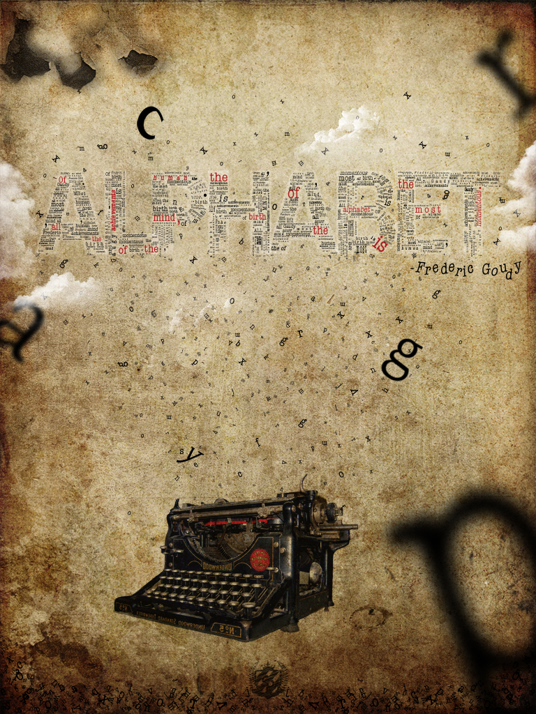
Realistic Crack
June 15, 2009 at 1:37 am | Posted in GrApHiX, PhOtOsHoP | Leave a commentTags: PhOtOsHoP, Photoshop Tutorial, Realistic Crack
This Photoshop tutorial shows how to create a crack in a stone texture. You will learn how to create a crack with variable thickness and you’ll create shadows and highlight without using a layer style. We will also explain how a layer set/group can be used to our advantage.
1. Adding the crack (highlight) |
In this Photoshop tutorial we’re going to use the following image:

You can save this image in Windows on your hard drive by right clicking on it and selecting Save Picture As…
(I don’t own a Mac, so I don’t know what the procedure is on a Mac).
Select the Pencil tool ![]() in the tool bar and choose a master diameter of 1 px by opening the Brush Preset picker window in the option bar:
in the tool bar and choose a master diameter of 1 px by opening the Brush Preset picker window in the option bar:
![]()
Create a new layer by clicking on the Create a new layer icon ![]() at the bottom of your layers palette and rename it to White crack by double clicking on its name in the layers palette.
at the bottom of your layers palette and rename it to White crack by double clicking on its name in the layers palette.
Press the letter D on your keyboard to make the fore- and background color black and white.
Press the letter X on your keyboard to switch the fore- and background color; the foreground color is now white:
![]()
We’re now going to draw the crack.
While holding down the left mouse key start in the top/left corner and draw a crack over a distance that’s about 1/5 of the final size of the crack. Once you’ve reached that point, release the mouse button but don’t(!) move the mouse, press the right bracket key ] on your keyboard once, to increase the master diameter of the pencil with 1 pixel and continue where you left off. Stop at 2/5 of the total length of the crack, release the mouse key again, press the right bracket key ] to increase the diameter another 1 pixel and continue drawing the crack.
At 3/5 of the distance you continue by using the bracket key [ instead to decrease the diameter to 2 pixels and you repeat this again at 4/5 so that you draw the last part of the crack with a diameter of 1 pixel.
The result could be something like this:

Make sure that you draw a random line with some sharp corners, a few bends and some straight parts.
At this point the beginning and ending of the crack stops too abrupt. We’re going to fix that by using a mask.
Add a mask to this layer by clicking on the Add layer mask icon![]() at the bottom of the layers palette.
at the bottom of the layers palette.
At that moment the mask is the active area (notice the double border and the mask icon ![]() in front of the layer (A)), so any further edits will take place on this mask only:
in front of the layer (A)), so any further edits will take place on this mask only:
Grab the brush tool ![]() in the tool bar and select a soft brush with a diameter of 40 in the option bar:
in the tool bar and select a soft brush with a diameter of 40 in the option bar:
![]()
Set the opacity of this brush in the option bar to 25%:
![]()
Make sure that your foreground color is black: ![]()
Now paint with black over the edges of the crack to make them fade (more transparent).
Use the following before & after rollover image as a guideline:

Continue by changing the blending mode to overlay in the layers palette and select an opacity of 75%
2. Adding the crack (shadow)

Press Ctrl + i (Command + i on the Mac) to invert the crack; it will now be black.
Important: the crack won’t look black when you look at it in your document window, since the layer’s blending mode is still set to overlay and the opacity is still 75%, since both were copied when we duplicated the White crack layer.
Change the blending mode of the Black crack layer in the layers palette to Color Burn, set the Opacity back to 100% and select a Fill of 85%:
With this layer selected, grab the Move tool ![]() in your tool bar and press the cursor right key
in your tool bar and press the cursor right key ![]() on your keyboard only once, then press the cursor up key
on your keyboard only once, then press the cursor up key ![]() also only once.
also only once.
At this point you should have something like this:

Notice that by using this method we’re blending the shadow with the actual texture of the wall, which results in fine visible details inside the crack which makes it all look slightly more realistic.
We’re now going to do a little trick to get rid of both identical layer masks, to end up with only one.
First click on the Create a new set icon![]() to create a new layer set (in Photoshop CS2 called a layer group).
to create a new layer set (in Photoshop CS2 called a layer group).
Now click on the mask that’s attached to the Black crack layer, hold down the left mouse key, move your mouse cursor until it’s on top of the Add layer mask icon![]() and release your mouse button:
and release your mouse button:
This will copy the layer mask that was attached to the Black crack layer to the layer set, since the layer set was the active layer at that time.
![]() In Photoshop CS2 we can duplicate a mask by holding down the Alt key (Option key on the Mac), click on the mask and drag and drop it onto the target layer:
In Photoshop CS2 we can duplicate a mask by holding down the Alt key (Option key on the Mac), click on the mask and drag and drop it onto the target layer:
Next we’re going to remove the masks of the Black crack and White crack layer by dragging (A) each mask to the Delete layer icon ![]() at the bottom of the layers palette. When asked “Apply mask to layer before removing?” simply click on the discard button:
at the bottom of the layers palette. When asked “Apply mask to layer before removing?” simply click on the discard button:


After removing the masks, continue by dragging the Black crack layer (B) to the layer set.
Do the same for the White crack layer (C).
Note: don’t drag the White crack layer first and after that the Black crack layer because then you end with the White crack layer as the first layer in our set, which is of course not what we want.
Continue by double clicking on the Set’s name and rename it to Crack:

I’m showing you all this to understand some of the advantages of layer sets/groups. At this point we can easily drag the crack around without having to worry about linking them. We can also easily drag the crack to a different document if we prefer to do so, because it’s now just a matter of dragging the set/group instead of the individual layers. We can now also easily hide the crack by simply clicking on the eye ![]() icon in front of the layer. Of course if we have multiple cracks it’s going to be a lot easier to keep the layers palette less cluttered when they’re all in one set/group.
icon in front of the layer. Of course if we have multiple cracks it’s going to be a lot easier to keep the layers palette less cluttered when they’re all in one set/group.
The other advantage, especially for this tutorial, is that we now have a single mask, which allows us to make a single change that will affect both the black and the white crack, which is important if we want to make the beginning or ending part of the crack fade away.
So go ahead, if you want to make some final adjustments to the mask, do that right now.
In the end we should have something like this:

Recent Comments

Blog at WordPress.com.
Entries and comments feeds.
